
Prepare the selected signal head’s terminal drawing and the controller’s output schedule before installation. This guide explains the information to check for 200mm and 300mm heads, modules and countdown configurations.
Updated 5 October 2026 · GAOQIAO Traffic Technology
Electrical installation and commissioning should be carried out by qualified personnel using the approved drawings and local requirements. Isolate the supply and verify it is de-energised before work.
1. Confirm the signal model and rated input
Read the rating label and identify the exact product and electrical version. The published 200mm three-aspect ball head and 300mm three-aspect arrow head list 12–24V DC or 110–220V AC options. Confirm the version supplied for your order against its rating label and approved drawing.
Record AC or DC input, rated range and frequency where relevant. Check the controller’s output type, rating and manufacturer-specified load compatibility. A nominal 200mm or 300mm size does not define the electrical interface.
2. Use the approved terminal drawing
Identify each conductor’s function from the model-specific drawing. Some heads use individual indication inputs with a common return; other assemblies have different connections. Wire colour alone does not establish function, polarity or a safe connection.
Match the drawing revision to the order and label the cable at both ends. For a replacement, provide photos of the rating label, existing connector and terminal block.
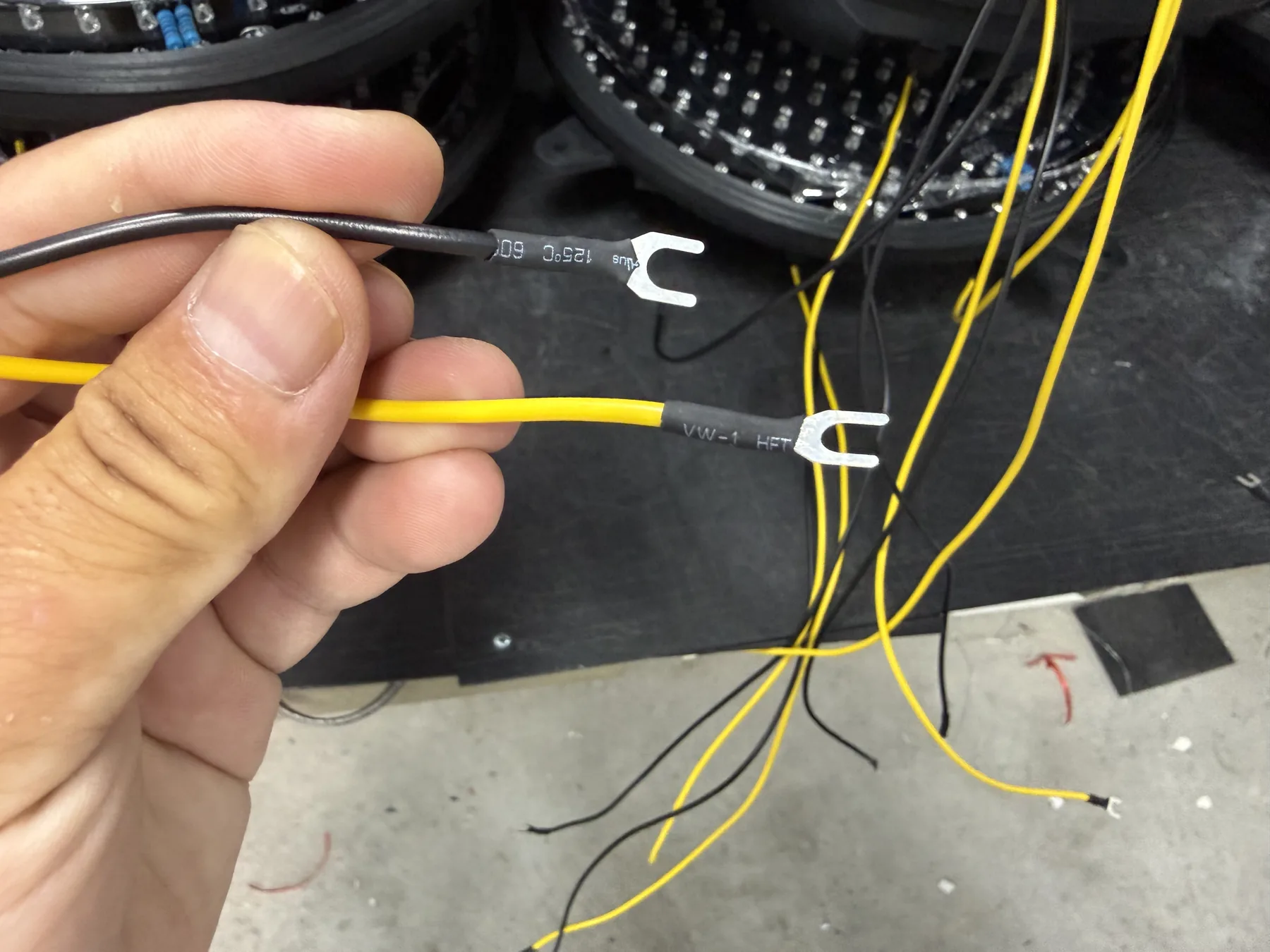
See the OEM wiring and label approval checklist for lead, connector and label information to confirm before production.
3. Build a signal-to-controller schedule
| Data field | Record from approved documents |
|---|---|
| Signal identity | Location/head ID, product model, electrical version and drawing revision. |
| Indication | Required ball, arrow, pedestrian or other display and its phase assignment. |
| Signal terminal | Terminal or connector pin, conductor function and applicable return arrangement. |
| Controller output | Output channel, terminal, output type and manufacturer-specified load limits. |
| Cable reference | Cable ID and the conductor identification used at both ends. |
| Associated equipment | Separate power or interface details for countdown displays and other devices, where fitted. |
Use the controller manual and approved signal schedule to verify phase mapping and conflict-monitor settings. See our controller compatibility guide and controller range for related selection information.
4. Check countdown and pedestrian interfaces separately
Identify the countdown model and its input method from the equipment documents. Supply, trigger, learning and communication arrangements vary by model. A product with a countdown display needs its own confirmed interface details.
Pedestrian buttons and audible devices also require their equipment-specific power and input connections. Include these devices in the wiring schedule and commissioning plan when they form part of the project.
5. Confirm the inspection and commissioning plan
Agree the required electrical checks, protective measures and indication tests with the qualified installer. Use test methods and limits specified for the equipment; verify any restrictions before insulation testing connected electronics.
Record the wiring and phase checks against the approved drawings. Verify each indication and any countdown or auxiliary interface under the project commissioning procedure. Keep the results with the head IDs and drawing revisions.
Information to send for a wiring review
- Signal model, label photo, rated input and quantity.
- Controller model, output specification and terminal schedule.
- Required indications, phase assignments and any countdown interface.
- Existing connector photos or the approved drawing for a replacement.
- Destination and applicable project requirements.
Download the enquiry checklist and attach your existing diagrams to the request.